Polarity Converter Wiring Diagram
If the signal source is equipped with a cross coupled output stage. If one pair uses pins 2 and 5 the other pair can use 1 and 3 1 and 4 3 and 6 or 4 and 6 but not 1 and 6 or 3 and 4.
 Understanding Dc Power Supplies Itp Physical Computing
Refer to Figure 1 below.
Polarity converter wiring diagram. Polarity markings on electrical drawings represent H1 which should be facing the source. I hope that was clear P Once your wiring is done setting the switch will cut off power allow it to pass through or invert the polarity respectively as shown in the diagrams below. This feature prevents permanent damage to the converter from a battery connected into the circuit backwards.
I will need to wire a dc converter for the power supply a timer the motor and I assume a relay. If converter fuses check good and 120 VAC. When you order 3-Wire Configuration youll get a White Black and a Blue.
What is the simplest wiring diagram that could achieve this. CT Polarity Electrical Drawing Conventions. Electrical Question from Gordon about Outlet Grounding Problem Background.
How to change polarity from a negative into a positive. The average fuel consumption on the Prius was 57 liters per 100 km. Most aftermarket alarms and remote starter boxes use negative outputs to control things such as doo.
The USB Wiring Diagram shows the USB data lines as vertical dotted lines ie VCC to Ground D2 to VCC GND to Ground and USB to VCC. Anyone else should feel free to change. DCC auto-reversers are also available to quickly detect a momentary short circuit and re-connect track polarity to a reversing track section.
The three most common schematic conventions are dots squares and slashes. How to Test CT. The 3 Wire configuration allows you to reverse the phase.
And there is power at the outlet. MC34063 is a 15A Step up or step down or inverting regulator due to DC voltage conversion property MC34063 is a DC-DC converter IC. In 2000 as a result of modernization engine.
Please verify all wire colors and diagrams before applying any information. Both motor legs rest at ground at the relays. If the signal source is equipped with an output transformer.
The diagram above assumes your volt meter black wire - is connected to battery - which emphasizes the 24 volt output of the converter. This makes the DROK voltage converter look more like the desired voltage inverter. Gordon a Homeowner from Los Angeles CA Question.
Perf board Solder wire and iron IC MC34063. A battery is installed a reverse polarity fuse protects the converter circuitry. The fuse is located along the bottom of the row of fuses.
Refer to Figure 1 below. My main issue has been in wiring the system to reverse the polarity. Wfco wiring diagram grand am engine diagram massey ferguson 35 rv converter wiring diagram dolgular 50 rv.
If converter output voltage reads 136 volts but the battery is still not charging check for an open automatic reset circuit breakerif provided or an open between the converter and distribution panel or an open wire between converter and RV Battery. This is practically identical to the 5 wire alternating 12V system. MC34063 pinout diagram has been shown in the below image.
For instance when you connect a printer to a computer the D2 is connected to the USB port on the computer DVCC is connected to the ground. Scroll to continue with content. Polarity should be no issue with these if you order your pickup with 3-Wire configuration.
The pins in each pair differ in polarity. I have one circuit in my house that appears not grounded on my plug-in circuit tester although the electrician I called tells me that the hotground voltage is around 66 volts. Changing your MG electrical system polarity is easy and cheap so dont even think about a polarity converter for your new radio.
Disconnect all battery cables from the batteries. This feature prevents permanent damage to the converter from a battery connected into the circuit backwards. Debuted in 1997 the Toyota Prius sedan became the first mass-produced car with a hybrid powerplant.
A battery is installed two reverse polarity fuses protect the converter circuitry. Any user assumes the entire risk as to the accuracy and use of this information. If the signal source is equipped with a pseudo balanced output stage.
The Positive Earth Society is for concours buffs. The microcontroller is fully automatic and requires no. The polarity marking on electrical drawings and diagrams may be made for current transformers in several different ways.
The Blue is chassis ground and should remain grounded. Joined Jul 18 2013 22298. He says theres probably a ground wire thats not tightly connected somewhere in the.
On the left side the internal circuit of MC34063 is shown and on the other side the pinout diagram is shown. The only difference is theres no switch. Your WFCO power converter is equipped with a microcontroller mounted on the converters PC board.
A gasoline engine 58 hp and an electric motor 40 hp powered by a battery. For either of these to be effective the protective circuit breaker must trip on an overload or the auto-reverser must re-orient track polarity faster than the main layout booster will trip. Thursday at 1026 AM 2.
Door Locks - Actuators Reverse Polarity - Negative SwitchTrigger Type D a Relay Wiring Diagram. Some TOYOTA PRIUS Wiring Diagrams are above the page. The fuses are located along the left-center edge of the DC fuse board below the VCC lug.
PRIUS Automatic Light Control Wiring Diagram. The diagram below is identical but assumes you have the volt meter back wire connected to battery. White is normally hot and Black is normally ground.
Van den Hul Audio CableConnector Wiring Diagrams Female Balanced XLR TO Male Unbalanced RCA Fig.
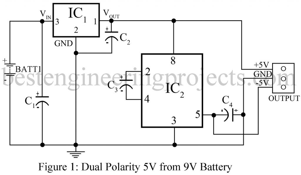 Dual Polarity 5v From 9v Battery Engineering Projects
 Simple Reverse Polarity Protection Circuit Has No Voltage Drop Edn
Convert A Negative Output To A Positive Output Relay Wiring Diagram
 P Channel Mosfet Drain Source Polarity In Power Switch Application Electrical Engineering Stack Exchange
 Wiring Diagram Help 6v Power Wheels Ride On Upgrade Electrical Engineering Stack Exchange


